The Simulate menu
- Auto propagate Ctrl-E
-
If checked, circuits viewed will be "live:" That is, the values propagating through the circuit will be updated with each poke or change to the circuit.
The menu option will be automatically unchecked if circuit oscillation is detected.
- Single Step Propagation Ctrl-I
-
Advances the simulation one step forward. For example, a signal may end up entering a gate during one step, but the gate won't show a different signal until the next simulation step. To help identify which points in the overall circuit have changed, any points whose values change are indicated with a blue circle; if a subcircuit contains any points that have changed in it (or its subcircuits, recursively), then it will be drawn with a blue outline.
- Reset Simulation Ctrl-R
-
Clears everything about the current circuit's state, so that it is as if you have just opened the file again. If you are viewing a subcircuit's state, the entire hierarchy is cleared.
- VHDL Simulation Enabled
-
Enables simulation of a VHDL entity in conjunction with third-party software.
Note : For VHDL simulation to work, third-party software must be installed and configured. Logisim will check for the presence of this software when saving or loading.
- Restart VHDL simulatior
-
Clears everything about the current circuit's state, so that it is as if you have just opened the file again.
- Go Out To State
-
When you delve into a subcircuit's state via its pop-up menu, the | Go Out To State | submenu lists the circuits above the currently viewed circuit's state. Selecting one displays the corresponding circuit.
- Go In To State
-
If you have delved into a subcircuit's state and then moved back out, this submenu | Go In To State | lists the subcircuits below the current circuit. Selecting one of the circuits displays the corresponding circuit.
- Manual Tick Half cycle Ctrl-T
-
Advances the clocks in the simulation by one tick when using the step-by-step mode. A clock set with a high/low duration of 1 tick will then advance by half a cycle.
This can be useful when you want to advance the clocks manually, especially when the clock is not in the same circuit as the one you are currently viewing. - Manual Tick Full Cycle F9
-
Same function as before, but advances by two ticks. A clock set with a high/low duration of 1 tick will then advance one complete cycle.
The other clocks of the project advance simultaneously in proportion to their parameters. - Auto Ticks Enabled Ctrl-K
-
Starts automatically ticking the clock. This will have an effect only if the circuit contains any clock devices (in the Wiring library). The option is disabled by default.
- Auto Tick Frequency
-
Allows you to select how often ticks occur. For example, 8 Hz means that ticks will occur eight times a second. A tick is the base unit of measurement for the speed of clocks.
Example: Tic high = 2, Tic low = 2, Clock = tic frequency / ( 2 + 2)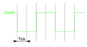
Note: that the clock cycle speed will be slower than the tick speed: The fastest possible clock will have a one-tick up cycle and a one-tick down cycle; such a clock would have up/down cycle rate of 4 Hz if the ticks occur at 8 Hz.
The number of ticks per cycle is defined in the High and Low Duration attributes of the clock component. - Timing diagram
-
Enters the logging module, which facilitates automatically noting and saving values in a circuit as a simulation progresses.
- Test Vector...
-
The window Vector of tests Allows you to check your circuits thanks to a test vector file that presents the inputs and outputs of the circuit.
- Assembly viewer
-
The Assembly viewer window displays an address value stored in a register and the assembly language instruction at that address.
Next: The Window and Help menus.