Oscillation errors
The propagation algorithm, which normally works silently without any problems, will become very visible when you create a circuit that oscillates.
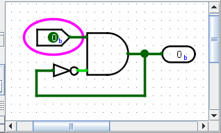
This circuit is currently in a stable condition. But if you change the input to 1, the circuit will effectively enter an infinite loop. After a while, Logisim will simply give up and show an "Oscillation apparent" message telling you that it believes that the circuit is oscillating.
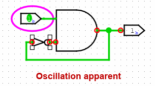
It will display the values it has at the time it gives up. These values will look wrong - in this screen shot, the AND gate is emitting 1 although one of its inputs is 0, but it could be that the NOT gate has a 1 input and a 1 output.
Logisim helpfully circles in red each location that seems to be involved in the oscillation. If an involved point lies within a subcircuit, Logisim will draw that subcircuit's outline in red.
When Logisim detects oscillation, it shuts down all further simulation. You can re-enable simulation using the menu | Simulate |→| Simulation Enabled |.
Logisim detects oscillation using a fairly simple technique: If the circuit simulation seems to many iterations, then it will simply give up and report oscillation. (The points it identifies as being involved are those that were touched in the last 25% of the iterations.) Thus, it could erroneously report oscillation, particularly if you are working with an exceptionally large circuit; but it would be one that is larger than any I have built using Logisim. In any case, if you are confident that the reporting is in error, you can configure the number of iterations completed before oscillation occurs via the Project Options window's Simulation tab.
Next: Shortcomings.