Using subcircuits
Now suppose we want to build a 4-to-1 multiplexer using instances of our 2-to-1 multiplexer. Of course, we would first create a new circuit, which we'll call Mux_4to1 To add 2-to-1 multiplexers into our circuit, we click the Mux_2to1 circuit once in the explorer pane to select it as a tool, and then we can add copies of it, represented as boxes, by clicking within the canvas.
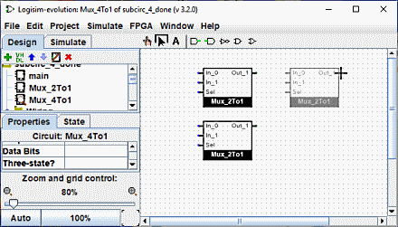
If you were to double-click the Mux_2to1 circuit in the explorer pane, then the window would switch to editing the Mux_2to1 circuit instead.
After building up the circuit, we end up with the following.
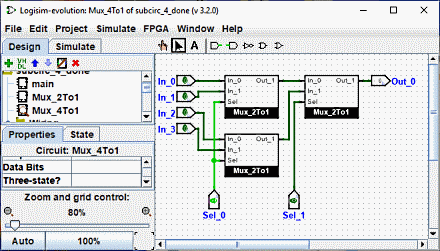
Our circuit for a 4-to-1 multiplexer uses three copies of the 2-to-1 multiplexer,each is drawn in a box with pins on the left and right sides. The pins on this box correspond to the input and output pins in the Mux_2to1 circuit. The two pins on the east face of the box correspond to the inputs of the circuit and on the west face they correspond to the output. They are read from the diagram of the sub-circuit from right to left and from top to bottom and they will be placed on the sub-circuit symbol from top to bottom.
If labels have been associated with these pins in the diagram they will be included in the symbol. In addition, they are also displayed as a tooltip when you fly over the pin with the mouse. You can disable this feature through the preferences panel .)
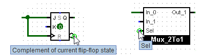
Several other components will display these tips, too: For some of the pins of a built-in flip-flop, for example, hovering over it explains what that pin does.
Incidentally, every pin to a circuit must be either an input or an output. Many manufactured chips have pins that behave as an input in some situations and as an output in others; you cannot construct such chips within Logisim (at least, in the current version.
Logisim will maintain different state information for all subcircuits appearing in a circuit. For example, if a circuit contains a flip-flop, and that circuit is used as a subcircuit several times, then each subcircuit's flip-flop will have its own value when simulating the larger circuit.
Now that we have the 4-to-1 multiplexer defined, we can now use it in other circuits. Logisim has no limits on how deeply circuits can be nested - though it will object to nesting circuits within themselves!
Note: There's nothing wrong with editing a circuit that is being used as a subcircuit; in fact, this is quite common. Be aware, though, that any changes to a circuit's pins (adding, deleting, or moving them) will rearrange them also in the containing circuit. Thus, if you change any pins in a circuit, you will also need to edit any circuits using it as a subcircuit.