 RAM
RAM
| Librairie : | Memory |
|
| Introduction : | 2.0 Beta 1 | |
| Apparence : |
|
Behavior
The RAM component, easily the most complex component in Logisim's built-in libraries, stores up to 16,777,216 values (specified in the Address Bit Width attribute), each of which can include up to to 32 bits (specified in the Data Bit Width attribute). The circuit can load and store values in RAM. Also, the user can modify individual values interactively via the "Poke" (![]() ) Tool, or the user can modify the entire contents via the
contextual menu . See Memory components in User's Guide
) Tool, or the user can modify the entire contents via the
contextual menu . See Memory components in User's Guide
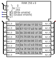
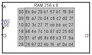
Current values are displayed in the component. Addresses displayed are listed in gray to the left of the display area. Inside, each value is listed using hexadecimal. The value at the currently selected address will be displayed in inverse text (white on black).
The RAM component supports three different interfaces, depending on the Data Interface attribute, Asynchronous read:, Data bus implementation et Enables:.
The Data bus type property allows you to modify the architecture of the data bus, either an omnidirectional Input and Data bus, or a bidirectional Data bus.- The default setting is a separate load and read bus with synchronous control.
-
A loading port controlled by the Store signal. A read port driven by the Load signal. Loading and reading are synchronized by the clock according to the trigger mode defined by the Trigger property. If both command lines are set to 1, then reading takes place after writing. This process can be reversed by modifying the Read behavior property.
- Asynchronous reading and activation of reading per byte.
-
If the Enables property is set to Use byte enables and the Asynchronous read property is set to Yes, only the state of the Load signal triggers the appearance of data on the output bus. Loading is carried out in the same way as before.
- Asynchronous Read and Use line enable.
-
If the Enables property is Use Line enables , and the Line size property is single, then the data will be immediately present on the output bus as soon as the address is changed. Loading is carried out in the same way as before.
- Synchronous Read and Use line enable. Several lines.
-
If the Enables property is Use Line enables , and the Line size property is different single then the data will be immediately present on the output bus as soon as the address is changed. For loading, additional signals LE1..LE7 allow selection of active data lines. The clock trigger mode is defined by the Trigger Trigger property. .
There are other more subtle settings, so please read the pin and property descriptions below for more details.
Pins
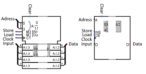
The Appearance attribute allows two different images for this component. Logisim Evolution presents inputs to the west and outputs to the east, while I present the pins from top to bottom and from west to east.
- Clear
- Input: This pin is only present if the Enables property is set to Use byte enables. When this is 1, all values in memory are pinned to 0, no matter what the other inputs are.
- Adress
- Input bus: Selects which of the values in memory is currently being accessed by the circuit.
- Store
-
Input: When activated, it authorizes data storage at the position defined by the value present on the Address bus. Depending on the values of the Trigger property, it is active at 1 on the Rising Edge/Lowering Edge values when synchronized by the clock signal. It is active at 1 on the High Level value and at 0 on the Low Level value independently of the clock signal.
Below you can see a table showing the different cases of memory write triggering according to the state of the various component properties.
Writing trigger modes Propriété Trigger Signal Clock Signal Store Lowering Edge ↑ 1 Rising Edge ↓ 1 High Level -- 1 Low Level -- 0 - Load
-
Input: This pin is only present if the Enables property is set to Use byte enables.
When active, it enables data transmission from the position defined by the value present on the Address bus.Below you can see a table showing the different cases of reading from memory to the output port, depending on the state of the various component properties.
Reading trigger mode Enables Trigger Asynchronous read ? Signal Clock Signal Load Use byte ebables Rising edge No ↑ 1 Use byte ebables Falling edge No ↓ 1 Use byte ebables High level -- -- 1 Use byte ebables Low level -- -- 1 Use byte ebables No effect Oui No effect 1 Use line ebables No effect -- No effect -- - Clock
-
Input : This pin is only present if the Trigger property is set to Rising edge/Falling edge, and in all other cases if the Enables property is set to Use line enables. When triggered, the memory will either save or present the data. The triggering mode is defined by the parameters of the Trigger property.
Look at the two tables above. - LE0 à LE7
- Input : These pins are only present if the Enables property is set to Use lines enables. Their number (2,4,8) depends on the Line size property. Each pin activates one of the input lines.
- Input
- Input bus : This bus is only present if the Data bus implementation property is set to Separate data bus for read and write. It receives the data that will be written to memory at the position specified by the value of the address pins when the trigger is triggered. See tables above.
- Input0 à Input7
- Input bus : These pins are only present if the Enables property is set to Use lines enables and the property Line size is different from Single. Their function is the same as that of the Input input, with this difference, Leur fonction est la même que l'entrée Input avec cette différence, Input0 points to memory location Address, Input1 points to address + 1, Input2 points to address + 2 and so on. Each input line has an associated enable signal LE0..LE7.
- Data
- Output bus: This bus is only present if the Data bus implementation property is set to Separate data bus for read and write Ce bus n'est présent que si la propriété Type de bus de données est positionnée sur deux bus omnidirectionnels. It transmits the data to be read at the position specified by the value of the address pins on triggering. See tables above.
- Data0 à Data7
-
Output bus: : These buses are only present if the Enables property is set to Use lines enables and the Line size property is other than Single. Their function is the same as the Data output, with this difference: Data0 transmits data from the memory position specified by the address pin value, Data1 transmits address + 1, Data2 transmits address + 2 and so on.
The Allow misaligned? property determines whether an error is generated when the address is not aligned to a multiple of the line number.
Attributes
When the component is selected or being added, the digits 0 through 9 alter its Address Bit Width attribute, Alt-0 through Alt-9 alter its Data Bit Width attribute.
- Address Bit Width
- Number of address bits. The number of values stored in RAM is 2Address Bit Width.
- Data Bit Width
- The data width in bits of each individual value in memory.
- Enables
-
Determines how data is presented to the component. Use byte enables: a single data bus is present.
Use line enables:one or more data lines make up the data bus. Each has its own selection signal. The Number of lines property lets you define the number of lines (1,2,4,8). - Ram type
-
Determines how the memory content is modified when the simulation is restarted:
Non Volatile memory contents are not modified.
Volatile; RAM contents reset to zero or randomly ( according to Simulation tab project options). - Use clear pin
- Determines whether the Clear pin is present or not. If this pin is set to 1, the memory content is asynchronously set to 0, and other commands have no effect.
- Line size
- These property are only present if the Enables property is set to Use lines enables Cette propriété est présente seulement quand la propriété Activation est positionnée sur Par ligne. Determines the number of data lines present at input and output 1,2,4 or 8. Each line is driven on loading by its own signal (LE0..LE7). Line 0 points to address 1, line 1 to address+1 and so on.
- Allow misalligned?
- These property are only present if the Enables property is set to Use lines enables.Determines whether data lines can interact with all memory addresses, or whether data lines are aligned with memory positions that are multiples of their number. For example, if you have two lines, the first line is linked to address + 0, the second to address + 1, and your addressing can only receive values that are multiples of 2, otherwise the outputs will be in error (E). See figure under Data0..Data7.
- Trigger
-
Configures how the clock input is interpreted. Values :
Rising edge indicates that the counter should update its value at the instant when the clock rises from 0 to 1.
Falling edge value indicates that it should update at the instant the clock falls from 1 to 0.
High level indicates that the memory should update continuously when the load input is at 1.
Low level indicates that it should update continuously when the load input is 0. - Asynchronus read:
-
Determines whether the clock signal is involved in the memory read process. Détermine si le signal d'horloge intervient dans le processus de lecture de la mémoire.
Yes means that only the load signal triggers reading.
No, reading will be triggered by the load signal and an edge of the clock signal. - Read begavior
-
Determines component behavior if read and write are enabled at the same time. Détermine le comportement du composant si la lecture et l'écriture sont activées en même temps.
Read after write : The data in the memory cell pointed to by Address will then be written, read and transmitted to the output.
Write after read : The data of the memory cell pointed to by Address will be transmitted to the output, then the value of the memory cell will be modified by the incoming data. - Data bus implémentation
-
Determines the architecture of the data bus. Values:
One bidirectional data bus: A bus is present for data input and output. Controlled buffers must be used to manage data flow.
Separate dat bus for read and write: Two buses are present, one for input and one for output. - Label
- The text within the label associated with the component.
- Label Font
- The font with which to render the label.
- Label visible
- If the label is visible or not.
- Appaerance
- Logisim-HolyCross / Logsim-Evolutions: New presentation of flipflops in the IEC way. Classic Logisim: Presents flipflops as the legacy of logisim
Poke Tool Behavior
See poking memory in the User's Guide.
Text Tool Behavior
None.
Menu Tool Behavior
See pop-up menus and files in the User's Guide.
Back to Library Reference