|
|
XOR/XNOR/
|
| Library: | Gates | |||||||||||||||
| Introduced: | 2.0 Beta 1 for XOR/Odd/Even; 2.0 Beta 6 for XNOR | |||||||||||||||
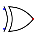
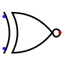
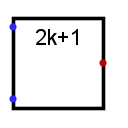
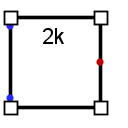
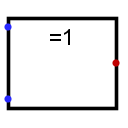
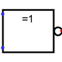
| Appearance: |
|
Behavior
The XOR, XNOR, Even Parity, and Odd Parity gates each compute the respective function of the inputs, and emit the result on the output.
By default, any inputs that are left unconnected are ignored — that's if the input truly has nothing attached to it, not even a wire. In this way, you can insert a 5-input gate but only attach two inputs, and it will work as a 2-input gate; this relieves you from having to worry about configuring the number of inputs every time you create a gate.
If all inputs are unconnected, the output is the error value (E). Some users, though, prefer that Logisim insist that all inputs be connected, since this is what corresponds to real-world gates. You can enable this behavior by going to the | Project | > | Options… | menu item and selecting the | Simulation | tab, and selecting Error for undefined inputs
for Gate Output When Undefined
.
The two-input truth table for the gates is the following. The letter E represents the error value, and the letter U represents the floating value.
|
|
|||||||||||||||||||||||||||||||||||||||||
|
|
|||||||||||||||||||||||||||||||||||||||||
As you can see, the Odd Parity gate and the XOR gate behave identically with two inputs; similarly, the even parity gate and the XNOR gate behave identically. But if there are more than two specified inputs, the XOR gate will emit 1 only when there is exactly one 1 input, whereas the Odd Parity gate will emit 1 if there are an odd number of 1 inputs. The XNOR gate will emit 1 only when there is not exactly one 1 input, while the Even Parity gate will emit 1 if there are an even number of 1 inputs. The XOR and XNOR gates include an attribute Multiple-Input Behavior that allow them to be configured to use the Odd Parity and Even Parity behavior.
If any of the inputs are the error value (E) (e.g., if conflicting values are coming into the same wire) or floating (U), then the output will be the error value (E).
The multi-bit versions of each gate will perform its one-bit transformation bitwise on its inputs.
Note: Many authorities contend that the shaped XOR gate's behavior should correspond to the odd parity gate, but there is not agreement on this point. Logisim's default behavior for XOR gates is based on the IEEE 91 standard. It is also consistent with the intuitive meaning underlying the term exclusive or: A waiter asking whether you want a side dish of mashed potatoes, carrots, peas, or cole slaw will only accept one choice, not three, whatever some authorities may tell you. (I must admit, though, that I have not subjected this statement to a rigorous test.) You can configure the XOR and XNOR gates to use parity by changing its Multiple-Input Behavior attribute.
Pins (assuming component faces east)
- West edge:
-
The inputs into the component. There will be as many of these as specified in the Number of Inputs attribute. Bit width according to Data Bits attribute.
Note that if you are using shaped gates, the west side of XOR and XNOR gates will be curved. Nonetheless, the input pins are in a line. Logisim will draw short stubs illustrating this; and if you overshoot a stub, it will silently assume that you did not mean to overshoot it. In "printer view", these stubs will not be drawn unless they are connected to wires.
- East edge:
-
The gate's output, whose value is computed based on the current inputs as described above. Bit width according to Data Bits attribute.
Attributes
When the component is selected or being added, the digits 0 through 9 alter its Number of Inputs attribute, Alt-0 through Alt-9 alter its Data Bits attribute and the arrow keys alter its Facing attribute.
- Facing
- The direction of the component, its output relative to inputs.
- Data Bits
- The bit width of the component's inputs and outputs.
- Gate Size
- Determines whether to draw a wider or narrower version of the component. This does not affect the number of inputs, which is specified by the Number of Inputs attribute; however, if the number of inputs exceeds 3 (for a narrow component) or 5 (for a wide component), then the gate will be drawn with "wings" to be able to accommodate the number of inputs requested.
- Number of Inputs
- Determines how many pins to have for the component on its west side.
- Output Value
-
By default the choice 0/1 indicates how false and true results should be translated into output values. By default, false is indicated by a low voltage (0) and true by a high voltage (1). With the 0/floting ou floating/1 choices one or the other can be replaced by a high-impedance (
floating
U) value instead. This allows wired-or and wired-and connections, as illustrated in the AND/OR/NAND/NOR Gate documentation. - Label
- The text within the label associated with the gate.
- Label Font
- The font with which to render the label
- Multiple-Input Behavior
- (XOR and XNOR only) The choice When three or more inputs are provided, the choice When on input is on determines that the XOR/XNOR gate's output will either be based on whether exactly one input is 1 (the default) or the choice When an odd number are on determines that an odd number of inputs are 1.
- Negate x
-
If
yes
, the input x is negated before it is fed into the gate. The inputs are counted top-down if the facing is east or west, and they are counted left-to-right if the facing is north or south.
Poke Tool Behavior
None.
Text Tool Behavior
Allows the label associated with the gate to be edited.
Back to Library Reference